How to Use a Laser Engraver for PCB and Component Labeling
I run a small electronics design studio — three engineers working mainly on power electronics and motor control boards. For the first few years, we outsourced all our PCB labelling. Every revision meant waiting on turnaround times and dealing with minimum order quantities. It worked, but it slowed everything down.

Eventually, I installed a fibre laser at the back of the workshop. The first job we ran was a batch of 30 development boards, each needing a unique serial number, a revision code, and our company logo. The whole batch took under an hour, and we had the boards ready the same day they were made. Looking back, it’s one of those upgrades I wish we’d made years earlier.
|
PCB LASER APPLICATION |
EQUIPMENT REQUIRED |
WHO USES IT |
|
Board labeling (serial, date, logo) |
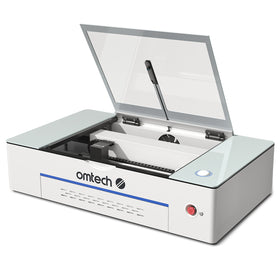
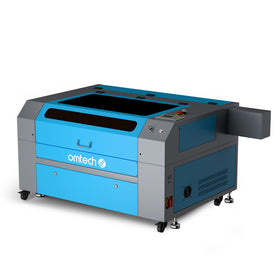
Fiber or CO2 laser |
Makers, small shops, contract assemblers, production |
|
Component identification marks |
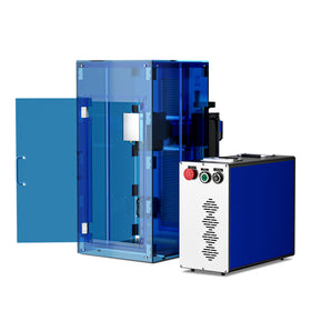
UV or fiber laser |
Electronics manufacturers, EMS companies |
|
Silkscreen text replacement |
Fiber or CO2 (FR4) |
Prototypers, small-run production |
|
QR / 2D codes for traceability |
UV or fiber laser |
Contract manufacturers, production lines |
|
Prototype PCB fabrication (trace etching) |
High-power diode or CO2 + chemistry |
Advanced makers, R&D departments |
|
Depaneling (board separation) |
UV laser (preferred) / CO2 |
EMS companies, flex PCB manufacturers
|
Laser engraving for PCBs and electronic components is far more versatile than most small labs and engineering teams realise. While much of the industry discussion focuses on high-end semiconductor marking, the practical reality is broader. Laser marking is now used across hobbyist builds, R&D prototyping, small-batch production, and contract manufacturing. In most cases, the goal isn’t to fabricate the circuit itself, but to add permanent identification — serial numbers, date codes, logos, and traceability markings — directly onto the board.

At its core, PCB laser marking is a non-contact process that creates permanent marks on the board surface without applying mechanical stress. This is particularly important in electronics, where even minor physical force can damage delicate traces or components. In practical terms, it allows engineers to label boards clearly and consistently without relying on stickers, ink, or external documentation. There is a distinction worth noting here. Laser systems can be used for PCB fabrication — removing copper to create traces — but that process is complex and typically limited to specialised R&D environments. For most workshops and manufacturers, laser engraving is used for labelling and identification, which is far more accessible and immediately useful.

In day-to-day use, laser marking solves a number of common problems. One small IoT company I worked with used to rely on adhesive labels for tracking their boards. During assembly, labels would shift, peel off, or occasionally end up on the wrong unit altogether. After switching to a fibre laser system, they began marking each board directly with a serial number and a 2D code before assembly. Those marks now survive soldering, cleaning, and handling without issue. More importantly, they’ve eliminated traceability gaps entirely, and the boards themselves look far more professional when presented to customers.

Choosing the right type of laser depends largely on the board material and the stage of production. Fibre lasers are the most common choice for PCB labelling, particularly on boards with dark soldermask such as green, black, or blue. These lasers interact well with the surface coating, producing high-contrast marks through controlled ablation or colour change. For many small manufacturers and design studios, a fibre laser strikes the right balance between cost, speed, and performance, especially when marking serial numbers or logos in batches.
CO₂ lasers, by contrast, interact with the organic materials in FR4 substrates, making them suitable for marking bare board material or cutting PCBs. Some makers use CO₂ systems for prototype work, particularly when combining laser processing with chemical etching techniques. However, there is an important safety consideration here. FR4 contains epoxy resins and flame retardants that release hazardous fumes when heated. Any use of a CO₂ laser on PCB material requires proper fume extraction and filtration. In many professional environments, especially in the UK where health and safety standards are strict, UV laser systems are preferred for cleaner operation.
UV lasers represent the higher end of PCB marking technology and are commonly used in production environments. They generate minimal heat and produce extremely fine, high-quality marks that can withstand soldering and cleaning processes. One of their key advantages is the ability to mark assembled boards without risking thermal damage to nearby components. While the initial investment is higher, UV systems are often the standard choice for manufacturers with strict quality and traceability requirements.
In practical terms, the workflow for PCB labelling is relatively straightforward once the system is set up. Most engineers export the board outline from their design software, such as KiCad, as a vector file. This is then imported into software like LightBurn, where the marking layout is defined. Serial numbers can be automated using variable text functions, allowing each board in a batch to be marked with a unique identifier without manual input. Once the laser parameters are calibrated for the specific soldermask colour, the process becomes highly repeatable. A simple fixture or jig ensures consistent positioning, and after verifying the first board, the rest of the batch can be processed quickly with minimal intervention.
The applications for PCB laser marking extend well beyond simple identification. Date codes and revision markings are among the most valuable additions, allowing engineers and service teams to track exactly when and how a board was produced. Logos and branding are also increasingly common, particularly for development boards and customer-facing products, where presentation matters. For production environments, 2D Data Matrix codes provide a direct link between the physical board and its manufacturing data, including test results and component traceability. Even in small labs, marking component references directly onto the board can reduce assembly errors and simplify troubleshooting.
As electronics continue to evolve, the need for smaller, more precise marking is only increasing. Modern components often leave very limited space for identification, which makes the precision of laser systems especially valuable. Fibre lasers can reliably produce readable text at small sizes, while UV systems can go even further for high-density applications. The key is always to balance visibility with material safety, ensuring that the mark is clear without damaging the board.
For many UK-based electronics teams, adopting laser marking is less about adding new capability and more about improving workflow. It removes the dependency on external suppliers, shortens development cycles, and ensures that every board is clearly and permanently identified from the outset. In an environment where traceability, quality, and efficiency all matter, laser engraving quickly becomes an essential tool rather than a luxury.